
Apply the right lubricant in the right pattern, volume, and location with dispensing hardware engineered around your process.
Kirkco designs lubrication dispensing systems for the controlled application of grease, oil, and other lubricant media across machinery, assembly stations, maintenance operations, and production lines. Dispensing options support dot or shot application, continuous flow, spray, and time-pressure methods for repeatable material delivery.
A complete dispensing system combines the valve with the supply pump, pressure-control equipment, delivery lines, controls, and—when required—flow or pressure monitoring. The result is a dispensing architecture selected around the lubricant, application point, cycle time, dispense pattern, and production environment.
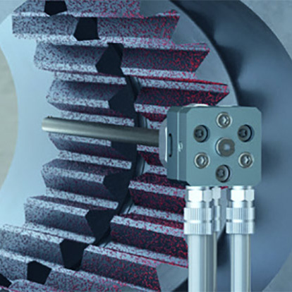
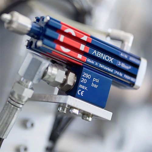

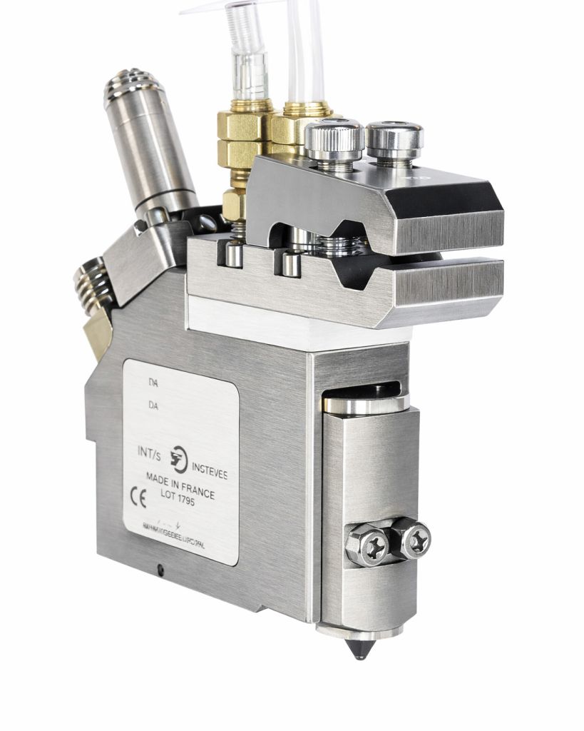
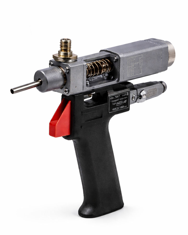
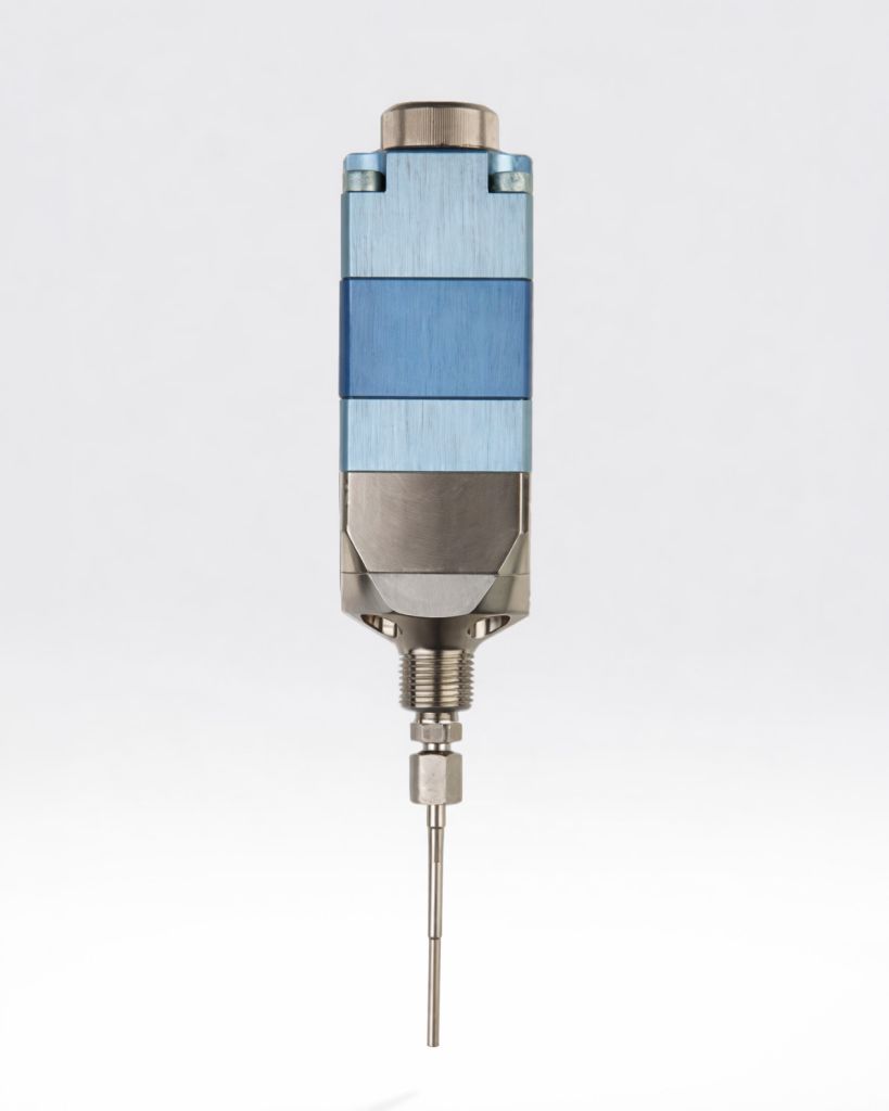
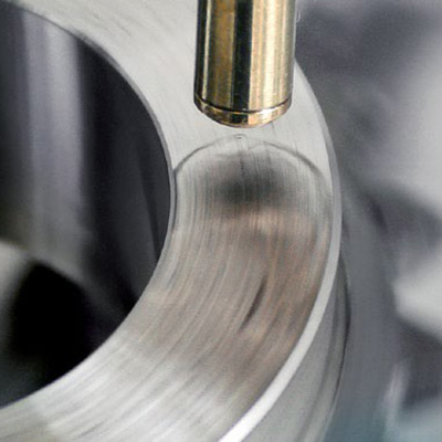
Lubrication dispensing is the final point of control between the delivery network and the machine, assembly, bearing, gear, guided surface, or maintenance location receiving grease or oil. The dispensing valve influences the material pattern, shot or flow behavior, response time, and ability to place lubricant consistently at the intended point.
Kirkco’s dispensing systems are designed to support repeatable lubricant output through dot or shot, continuous, or time-pressure methods.
Engineering Engagement
Ready to Engineer Your Next System?
Kirkco supports confidential engineering engagements under NDA. Discuss your application requirements with our team and receive a system architecture tailored to your process.
A dispensing valve should not be selected in isolation. Pumps move grease or oil from drums, cartridges, or bulk tanks to the dispense point, while regulators help stabilize pressure and compensate for line pulsations. The valve then applies the material in the required pattern, volume, and timing.
Different dispensing patterns require different valve architectures. Use the following guide as a starting point, then confirm the selection against the lubricant, required volume, cycle time, pressure, and application geometry.
Spray valves
Broad or distributed lubricant coverage and continuous film application
Shot dispensing valves
Defined grease or oil shots at bearings, gears, guided surfaces, or assembly points
Needle dispensing valves
Targeted application to small or difficult-to-reach lubrication points
High-speed dispensing valves
High-cycle production lines requiring rapid valve response and repeatable dispensing
Handheld dispensing valves
Maintenance stations, service operations, and operator-directed lubrication
Diaphragm dispensing valves
Controlled grease or oil dispensing where diaphragm operation and material isolation are appropriate
Shot dispensing delivers a defined amount of grease to a specific lubrication point. This approach is useful for bearings, gears, guided surfaces, pivots, and other locations where the application requires a repeatable dose rather than a continuous film. The shot volume, pressure, valve response, lubricant viscosity, and cycle timing should be validated together.
Continuous dispensing applies grease or oil over a defined period or path. It can support conveyor systems, guided surfaces, long lubrication paths, or applications that require a continuous film. Flow stability depends on the pump, pressure regulation, lubricant behavior, delivery-line design, valve, and desired application rate.
Time-pressure dispensing uses a controlled pressure and dispense interval to deliver lubricant. It can be appropriate when the required output is defined by the relationship between pressure, time, valve opening, and material behavior. The delivered volume should be checked under representative conditions because viscosity, temperature, supply pressure, and line resistance can affect the result.
Spray valves can apply lubricant across a broader area or create a distributed film. The system should be evaluated for spray pattern, material viscosity, flow rate, air or pressure requirements, overspray, containment, and the effect of nearby components or surfaces.
A dispensing system can be monitored through micro-flow sensors or pressure sensors mounted on the dispensing valve or within the lubrication network. These signals can help identify whether lubricant is moving as expected, whether pressure is within the intended range, and whether a dispensing event has occurred.
Monitoring should be matched to the process risk. A simple maintenance station may require visual confirmation and operator control, while an automated assembly line may require pressure monitoring, micro-flow feedback, cycle confirmation, or a machine interlock.
Automated assembly lines often require frequent, repeatable lubrication at defined machine-cycle locations. A dispensing architecture can synchronize shot or continuous application with the assembly sequence, direct lubricant to multiple points, and use sensors or machine controls to verify the event.
The system should be designed around the number and location of lubrication points, the required shot or flow volume, cycle rate, lubricant supply, access to the application point, and the level of feedback required by the production process.
Bearings, gears, pivots, and guided surfaces may require a controlled grease dot rather than broad-area coverage. Needle or shot dispensing valves can be evaluated for targeted placement, while pressure regulation and metering control help maintain consistent delivery as line conditions change.
The appropriate architecture depends on the grease, target volume, nozzle access, surface geometry, lubrication interval, and required tolerance for variation. The goal is to place enough lubricant at the intended point without relying solely on operator judgment or inconsistent manual application.
Conveyor systems and other moving surfaces may require continuous or distributed oil application rather than discrete grease shots. Spray valves or continuous-flow dispensing can be evaluated around line speed, lubricant viscosity, coverage width, flow rate, containment, and the potential for overspray or migration.
Control of pressure and flow is important when the application must maintain a stable film across a moving surface. The system should also account for the supply distance, delivery-line routing, operating environment, and maintenance requirements.
Maintenance stations may require operator-directed dispensing at multiple machines or service points. Handheld valves can provide flexibility for maintenance teams while reducing the need to move heavy supply equipment to each location.
Selection should consider valve weight, hose management, trigger or actuation method, lubricant viscosity, operator reach, dispensing volume, and the desired level of documentation or verification. A handheld architecture can also serve as a practical step toward more standardized maintenance lubrication.