

WADS
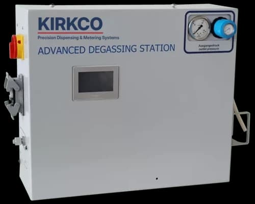
Advanced Degassing Station
Finds air and gas pockets in grease and high-viscosity lubricants, discharges only the contaminated slug, and keeps bubble-free material flowing to your dispense valve without stopping production.
Why degas
Air in the material is air in the part.
Gas inclusions get into grease during drum changes, pump priming and line maintenance. Once they reach a metering valve, every shot that carries a bubble is a short shot.
- 1.3 mm
- Smallest detectable bubble (0.051 in)
- NLGI 3
- Greases and oils up to NLGI grade 3
- 150 bar
- Maximum inlet pressure (2,175 psi)
- 2,000 cm³
- Internal buffer keeps supply running during discharges and drum changes
Under-dosed parts
A bubble takes the place of material in the metered volume, so the part receives less lubricant than specified, and repeatability drops with it.
Contamination and mess
Compressed air expands at the nozzle and spits material onto the part and fixture, creating cleanup and rework.
Valve wear
Pressure spikes and dry cycling caused by entrained air damage dosing valves and shorten service intervals.
How it works
Scan the stream, reject the bubble, restore the pressure.
The station sits in the supply line between your pump and your application equipment. Material passes through six stages inside one wall-mountable cabinet.
Degassing station cabinet
- 20–150 barSupply
- 1Pressure reduction
- 2Flow restriction
- 3Bubble detection
- 5Buffer container
- 6Booster pump
- 0–200 barTo valve
Bubble-free material continues to the valve. When gas is detected at stage 3, stage 4 diverts only that slug to the collection bottle.
1
Pressure reduction
A regulator drops the incoming pressure so trapped gas expands and bubbles grow large enough to detect reliably.
2
Flow restriction
An orifice slows the stream so every bubble passes the sensor at a speed it can resolve.
3
Bubble detection
The detection module counts and sizes bubbles against limits you set, down to 1.3 mm at the highest sensitivity.
4
Targeted discharge
When gas is found, a valve diverts only that portion of material to the collection bottle. Good material stays in the line.
5
Buffer storage
A pressure-controlled container holds degassed material, so the outlet keeps feeding during discharges and supply-drum changes.
6
Pressure boost
An adjustable booster pump brings the material back to line pressure, or higher, up to 200 bar at the outlet.
Inside the cabinet
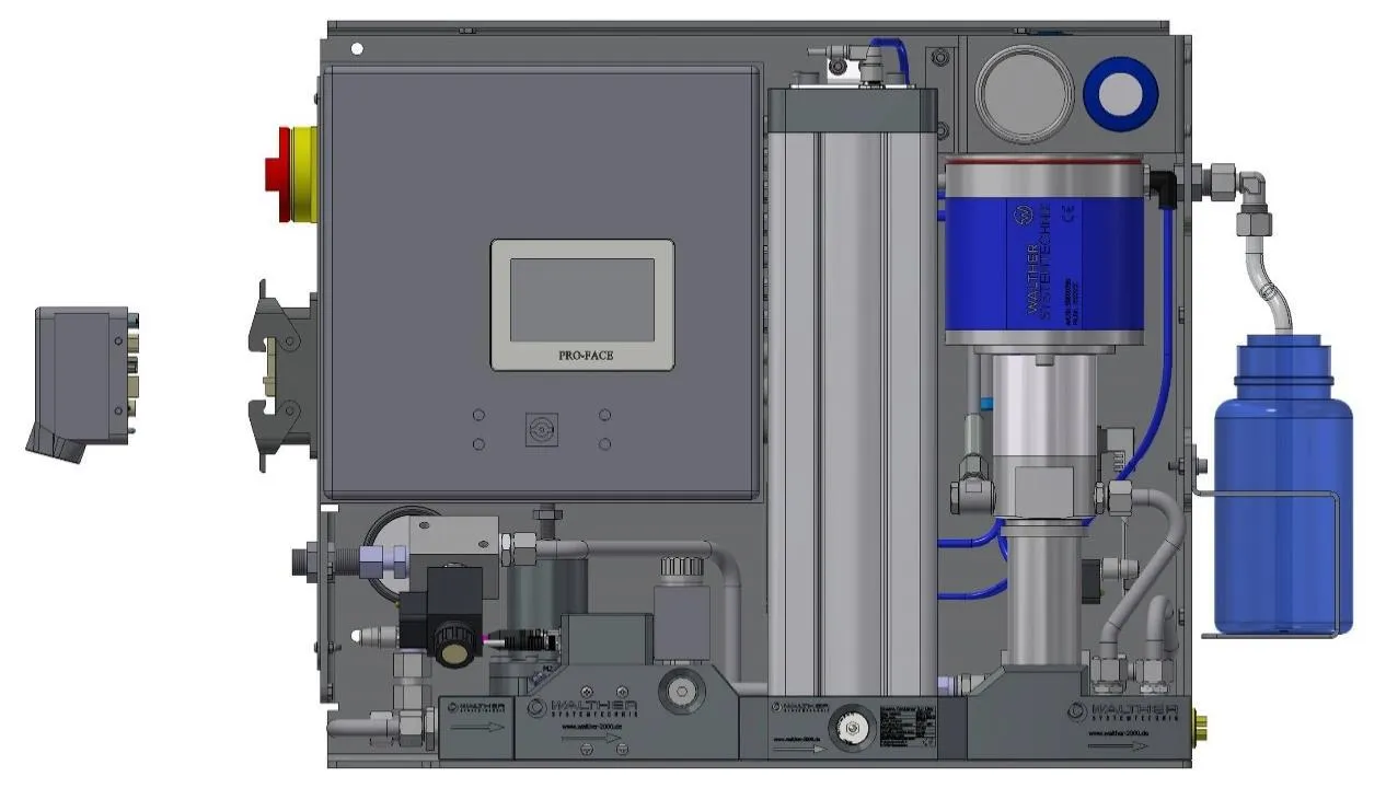
- ASingle plug for power, bus, I/O and air
- BControl cabinet with touchscreen
- CPressure reduction, flow restriction, bubble detection and discharge valve (stages 1–4)
- DBuffer container (stage 5)
- EBooster pump (stage 6)
- FCollection bottle for discharged material
Benefits
More stable process, fewer rejects.
Higher process capability and OEE
Consistent bead and shot volume improve Cpk and reduce scrap and rework.
Minimal material loss
Only the contaminated portion is discharged, not a timed purge.
Continuous supply
The internal buffer feeds the application during discharges and container changes.
Retrofit or new build
A self-contained unit that fits into an existing supply line or is designed into a new system.
Built-in monitoring
Tracks bubble count and size, discharge time and buffer level, and alarms on any limit you define.
Control and integration
- Local
- Stand-alone operation from the built-in 4.3 in touchscreen; manual and automatic modes
- Remote
- Full control and parameter setting from your PLC over Ethernet (Modbus TCP)
- Discrete I/O
- 3 digital inputs, 3 + 3 digital outputs
- Alarms
- 4 freely configurable 24 VDC alarm outputs for high/low limits on monitored values
- Connection
- Single industrial plug carries power, bus, I/O and compressed air
- Security
- Password protection against unauthorized setting changes
- Diagnostics
- Fault log, empty-buffer stop, buffer-level monitoring
Technical data
Specifications
| Parameter | Metric | U.S. |
|---|---|---|
| Fluid | ||
| Inlet pressure | 20–150 bar | 290–2,175 psi |
| Outlet pressure (adjustable) | 0–200 bar | 0–2,900 psi |
| Average volume flow | max. 100 cm³/min | 6.1 in³/min |
| Short-term volume flow | max. 1,500 cm³/min | 91.5 in³/min |
| Buffer storage volume | 40–2,000 cm³ | 2.4–122 in³ |
| Buffer storage pressure | max. 10 bar | 145 psi |
| Suitable media | Non-abrasive oils and greases to NLGI 3; particle size < 150 µm | |
| Bubble detection | ||
| Highest sensitivity | ≥ 1.3 mm | 0.051 in |
| Lowest sensitivity | ≥ 4 mm | 0.16 in |
| Utilities | ||
| Supply voltage | 110 or 230 VAC | 16 A max. fuse |
| Control voltage (I/O) | 24 VDC | — |
| Compressed air | 4–10 bar | 58–145 psi, clean, dry, oil-free |
| Connections | ||
| Material inlet | 12L 24° cutting-ring tube fitting (12 mm tube) | |
| Material outlet | G 1/2 (BSPP) | |
| Physical | ||
| Dimensions L × W × H | 739 × 268 × 514 mm | 29.1 × 10.6 × 20.2 in |
| Weight | 18 kg | 40 lb |
| Enclosure rating | IP66 | — |
| Operating temperature | 10–40 °C | 50–104 °F |
| Mounting | Wall, frame or flat surface; 4 × M8 mounting points | |
| Wetted materials | Stainless and carbon steels, PTFE, FKM, polyurethane, NBR | |
U.S. values are converted and rounded. Contact Kirkco for the full data sheet and installation drawing.
Application fit
Is your material a candidate?
Good fit Yes
- Greases and high-viscosity oils up to NLGI 3
- Non-abrasive media with particles under 150 µm
- Automated grease metering on assembly lines (automotive, appliance, electromechanical components)
- Processes with short shots, spitting or rejects traced to air in the material
- Lines where drum changes introduce air into the supply
Not suitable No
- Abrasive or heavily filled media
- Acids, alkalis, cleaning agents and aggressive chemicals
- Polar solvents such as acetone, MEK or ethyl acetate
- Hazardous (explosive) atmosphere locations
Not sure? Send us the product data sheet for your material and we will review it.
Delivered by Kirkco
Part of a complete lubrication system, not a box on the floor.
Degassing only pays off when the supply in front of it and the metering after it are matched to your material and cycle. Kirkco engineers the whole line and stands behind it.
- Drum or pail pump
- Advanced Degassing Station
- Pressure regulator
- Metering valve
- Your part
Application engineering
We size supply, degassing and metering together from your material, shot size and cycle rate, and integrate the station with your PLC.
Installation and training
In-field installation, commissioning and operator training from the team that designed the system.
Service and repair
U.S.-based support, rebuild and repair for the full metering line, backed by nearly 40 years of grease metering experience.
Kirkco supplies this station through its precision dispensing partnerships, including ABNOX and Walther Systemtechnik.
Common questions
FAQ
Can it be added to an existing grease system?
Yes. The station is self-contained and installs in the supply line between your pump and your metering equipment. Kirkco can review your current layout and recommend where it should go.
Does production stop when a bubble is discharged?
No. The internal buffer keeps feeding the outlet while the discharge valve diverts the contaminated material, and during supply-container changes.
How much material is wasted?
Only the portion of material that contains the detected gas is discharged. There is no timed purge of good material.
Can my PLC control it?
Yes. Every setting and process value is available over Modbus TCP, and digital I/O covers simpler start, stop and alarm wiring. It can also run stand-alone from its own touchscreen.
Let us help you select what you need
Talk to a Kirkco engineer about air in your process.
Tell us about your material and application and we will recommend the right degassing, supply and metering setup.
Helpful to have ready
- Material name, data sheet and NLGI grade
- Shot size or bead rate and cycle time
- Current supply pump and line pressure
- Metering valve or dispense equipment in use
- PLC platform, if remote control is needed
- What you see today: short shots, spitting, rejects